Arduino Stepper Motor Serial Control Video

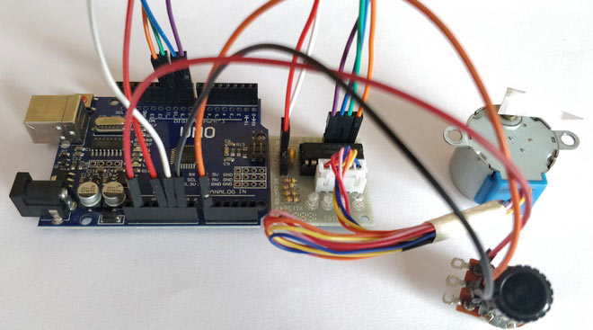
Learn Arduino, Lesson 16. Stepper Motors. Which pins are connected to the motor controller. For our new TTL serial camera module with NTSC video.
Stepper stepperoneStepAtATime One step at a time Stepper motors, due to their unique design, can be controlled to a high degree of accuracy without any feedback mechanisms. The shaft of a stepper, mounted with a series of magnets, is controlled by a series of electromagnetic coils that are charged positively and negatively in a specific sequence, precisely moving it forward or backward in small 'steps'. There are two types of steppers, Unipolars and Bipolars, and it is very important to know which type you are working with. For each of the motors, there is a different circuit. The example code will control both kinds of motors. See the and motor schematics for information on how to wire up your motor. In this example the motor will step one step at a time, very slowly.
You can use this to test that you've got the four wires of your stepper wired to the correct pins. If wired correctly, all steps should be in the same direction. You may also use this sketch to count the number of steps that your motor does in one revolution.

Overview

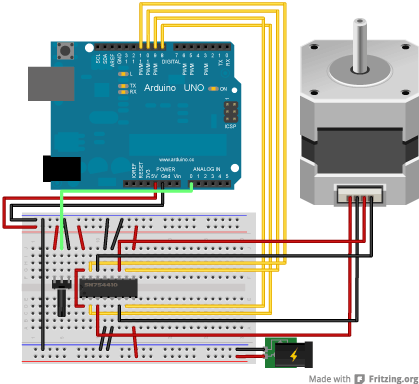
Breadboard Layout
The stepper is controlled by with digital pins 8, 9, 10, and 11 for either unipolar or bipolar motors. The Arduino or Genuino board will connect to a if you're using a unipolar stepper or a if you have a bipolar motor. For more information about the differences of the two types, please take a look.